I decided to add a tube reverb I made years ago to my arsenal to take to the radio show and trialed it just before I chucked all the stuff into the car for the trip into town. I wanted it just after the first booster and before the phaser and subsequent digital delay so when I was on the backwards delay I could add reverb to it, backwards reverb sounds good!
I hadn’t used the reverb for ages simply because I was never happy with it but on setting it up it gave enough of a result to be worth taking. Trouble was that the power switches were wired in upside down and because of the kinda hurried nature at the radio, the previous guys ran over then one, who plays mean cello, kinda kept me talking when I should have been setting up… so I was late, a little nervous and couldn’t figure why my reverb wouldn’t go, all the while having about 40 seconds left to get sounds so I ditched it, bypassed it, and turned it all on and got some levels. God, what a debacle it was.
I mean I did have fun with it but it was all so hurried and I talked a bit much at the beginning so there wasn’t much time for music at the end and Chris, whos the drummer extraordinaire around town, was kinda waiting to get the jazz show started…
Anyways the long and short of it all is that I took the reverb home and sat in front of it and decided it was worth the effort to either tweak up or rebuild. Conventional spring reverbs are of the fender type where a valve is connected to an output transformer, smaller than a normal one as its only driving the reverb tank, which then transforms the valves high impedance output to a much smaller impedance, 8 ohms, to drive the tanks inductor. But since semiconductors came along the folks at Accutronics in Illinois have been building higher impedance tanks to suit the outputs from opamps. I got one of those because you can actually use valves to drive them but without the weighty and expensive transformer.
But my build suffered from not enough drive to the tank and too much clean signal so it needed lots of boost, with a subsequequent raising of the noise floor, and even then wasn’t the full lush reverb wash I wanted.
With that in mind I decided on a rebuild and after having found a page devoted to using tubes on all the accutronics reverb tanks; low, medium and high impedance inputs, I decided also to change the parallel’d up medium mu (mean basically means voltage amplification factor) valve with a low mu type which, though lower in voltage amplification also means high in current amplification.
Well thats all well and good to decide to use a specific valve but what if you haven’t got one or you have a similar one that runs at another filament voltage? It’s all about choices really, working through them until the compromises suit the outcome you require. At the moment the reverb has two 12SL7 dual triodes so I was going to replace one of the valves with a 12SN7 ( which is similar to the 12AU7) but I haven’t got any 12SN7’s but I do have a couple of 6SN7’s… but the only 6SL7 I have is in an amp…?
I can use 12V valves or 6V valves as the filament supply I have on the reverb is 12V so I can parallel up 12V valves or have two 6V valves in series. I could have used a 12AU7 but those are more modern 9 pin small glass and the ones I’m currently using are octals which sit on bakelite bases and are much bigger and aesthetics are important to me.
So I made my decision to take the 6SL7 out of the moonlight amp and interchange it until another one arrives. So last night I gutted the reverb and rewired the chassis for two 6V valves in series. I’d also drawn up a schematic and etched a board to use pins in a style that predates PCB’s but postdates point to point wiring. This particular style of working allows you to change parts easily as you tweak the design.
This is a major consideration with valves because they often need various parts changed but point to point wiring, which very good for long term use, is very hard to cut into to make changes on the fly.
My next consideration is whether the back to back power transformers I have will supply enough power now that I’ve added a lower voltage amplication/ higher current amplification tube. The 12SL7’s are biased for about 1 – 2 mA whereas the 12SN7’s require at least 5mA and when using back to back transformers that small difference is quite considerable as the change fro 12V up to 240V is x20 so the current needs are also x20.
The back to back thing works where the first 240/12 transformer supplies the filament voltage and current, 6SL7 and 6SN7 require 900mA, and then you go back into the low voltage windings of another transformer and out the other end your back up to high voltage for the valve plates. The transformers I’ve got are 15VA which means Volts Amps, which is basically Watts, so 12.5 Volts, the filament voltage, divided by 15VA = 1.25 A – .9 =.35. That means I have 350mA at 12V to chuck into the next transformer. The voltage goes up and so the current goes down and . I decide to go into the 15V winding which give me a B+ of 190Vrms and a peak voltage of 270VDC. Into the 15 and out the 240 is a change of 16 so my .35A becomes .021 or 21mA… oops I’m going for peak voltage so the 21mA is divided by .7 which leaves me 7/10’s of 21 which is about 15mA which is just about enough to drive two 6SL7 triodes and two current hungry 6SN7 triodes in parallel.
This is the trouble with not having so much money. You have to do all these calculations to see whether what you’ve got will suffice while also, already having just enough, whether you can push what you have to acheive a little bit more. After all the calculations and looking in boxes and scouting about for parts I can basically rebuild the reverb and only spend about 5 bucks for parts I haven’t got in stock and also have something I can go back into easily to tweak it up.
Before photos go in, I’ll keep you waiting, I also dropped into the rockshop after the interview and had a good look at the Orange Tiny Terror and surmised that it’s size and kinda outlook would be good for an amp I’ve been planning for a while now.

It’s a valve amp switchable between 15 and 7 watts output and runs in class A. Upon getting home I found the schematic and it’s basically a Vox AC10 with a few AC15 ideas to modernise it and it’s output in class AB1 style push pull with the tubes biased really hot and into class A territory. Not quite what I wanted, but I could do it as I have a spare push pull output trannie, but I really wanna do the class A thing single ended. Much more second order, octave, distortion with SE than anything else and thats where warm, cuddly and FAT really happens with valves.
The moonlight just ain’t big enough anymore, plus I’m robbing the 6SL7 from it, and the big amp with multi channels still seems rather a task to get going so it’s definitely on the boards to make a tube amp for performing before the end of the month. Plus I’ve still got two twelve inch speakers so maybe my version of a fenderish twin, of sorts, thats actually more champish with Vox AC10 style preamp…
Incidentally I came across a Weber site that explained the difference between the amounts of ribs on these speakers and how they affect breakup. No ribs, early breakup, some ribs, medium breakup and all ribs… late breakup. My quads got all mediums, the amp I just almost finished has all ribs and I’m pretty sure the last two boxes contain no ribs… which be just right for a single ended amp. I actually want that Neil young ultra saggy and comp’d sound where the amp sounds like it’s straining sound through a three hundred year old set of gold threaded turkish courtisans fishnet stockings. Kinda shady relics as it were.
Now photos.
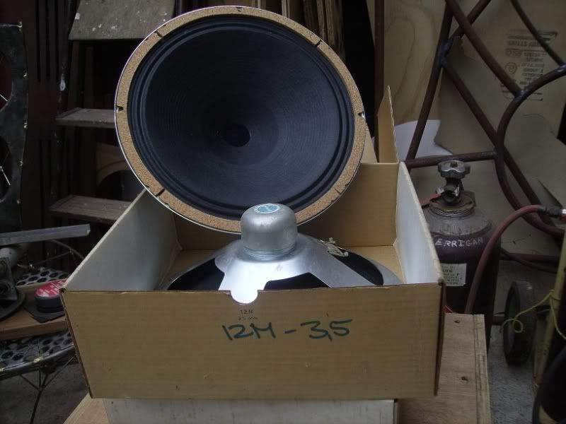
Boringest first. Two old NOS (new old stock) Plessey 3.5 ohm 12″ alnico paper, unribbed, speakers of about 10W.
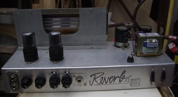
Then we have the old reverb, which I’ll box up in Macrocarpo or Kauri, and you can see in this photo that I modified the reverb tank cage so I can get access to the springs…
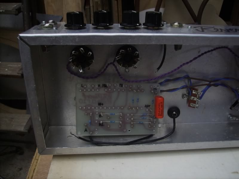
And in this you can see the detail of the new board, which is called turret board, because the little pins that stick up from the board are turrets, and they allow you to wind the ends of the caps and resistors around the pins and solder them on and that process makes removal and changing values quite easy and no dissemble to make tweaks. Wires then run to the pots and power supply, valves etc.
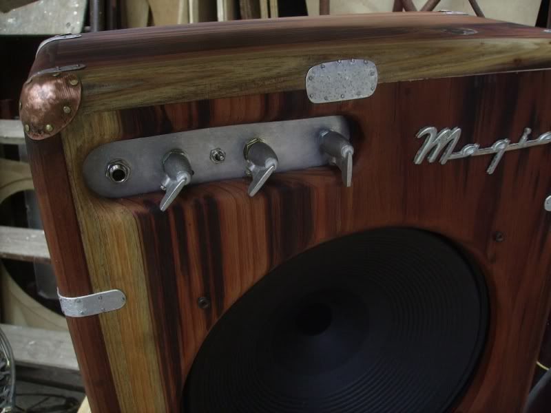
Then we have my new amp, which still needs a grill over the speaker to protect it, a set of feet and a handle for carrying it about but for all intents and purposes it is ready to be plugged in… which I still haven’t done yet so I hope it works!
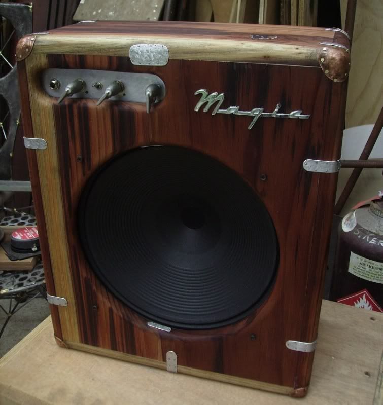
I oiled up the box with some mixture I bought years ago from the Onehunga woodwork tool shop, not quite as good as the oil I got from Patamahoe that’s long gone, but still quite nice, then dirtied it all up again after the process of making the copper corner pieces so I had to resand with wet and dry, using turps, to clean it up of all the smudges, then re-oil it. The knobs are some pewter ones I had cast up a few years ago and the magic badge? Well, like magic itself, I have no idea where I got it from and what it was about but I believe in it so it works!
This is what it looks like from the back, and after reading the Pignose patent notes a few days ago, I’m thinking of covering the rest of the back with a hinged cover, like a window with catches and stuff, so I can set the amount of energy that comes out the back.
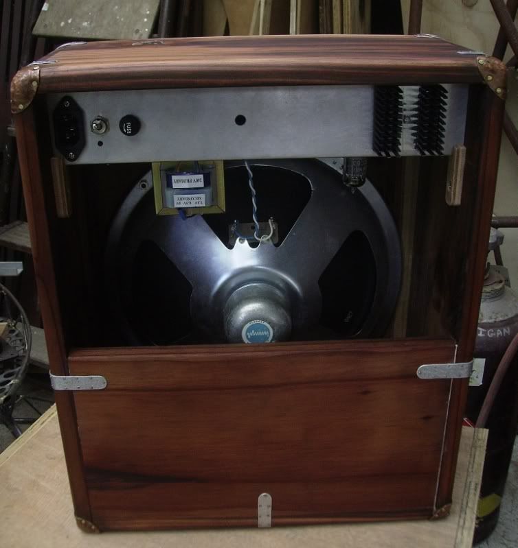
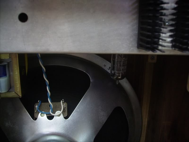
And if you look closely at the above photo you can just see the ECC83 phillips, made in Holland, thermionic valve, but I’ve made it easier (see below). The only thing that concerns me about this build is that B+ and the filament voltage come on at the same time which can mean cathode stripping because the filaments take 11 seconds to warm up and as this happens the plates are at high voltage almost straight away so electrons are immediately ripped from the filament winding and this isn’t a good thing.
Down the bottom of this page , though he doesn’t say it straight out, is a possible way to solve the cathode stripping problem ( thats why valve amps have the extra switch to allow the filaments to warm up before the B+ is turned on; standby). He puts an LED above or below the plate resistor which takes a few seconds to come on and this alleviates the cathode stripping somewhat. Hard to believe you can pass 250V + accross a part that won’t take more than 2V but if he says it’s so then it must be true. It is just a diode though and the fact it not at eart then… I’m just wondering about the current.
So there you go. The valve Wizards pages are very good for understanding how to use valves and how to set them up optimally once you’ve done the background reading ( the .pdf’s by Norman H Crowhurst at Audioexpress.com) and the next one I’ll be into, after the SE amp is the SRPP thing at the bottom of the linked page to fire a bunch of low impedance reverb tanks I have from old amps and organs.
