
So I’ve basically nutted out the schematic for the tube amp and I’ve done all the mechanical stuff so it’s full steam ahead wiring it all up. All the power supply stuff, filaments, grounds and most of the output pentode wiring is point to point and sits under the preamp board. Just a little more to do, well actually the whole other side, opps I forgot, which is all the wiring for the pots… but then the board goes in.
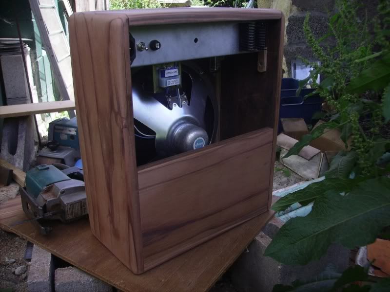
So heres a photo without the board.

and heres one with the preamp board covering it up

Now if I can go through my old stuff and find one more 1 Meg log pot I’ll be able to start on the control stuff.
The first attempt at etching a board failed somewhat as the sharpie ink tends to not like long traces because each time you lift off the pen you get a slight edge that doesn’t cover so I did this one using acrylic screenprinting fabric ink with a small brush then tidied it up with the edge of a knife then set it with the heatgun and it worked well. No eating through at all. I now use a fairly high concentration of hydrogen peroxide to hydrochloric and it eats out a board in under two minutes… Bit dangerous though. Chlorine gas isn’t very tasteful.
Because it puts it out there.
Okay, suddenly I need to get my shit together and learn my chops.
Well not really but at the least I have to look as if I have. Actually the answer might be that being such an avid firestarter it’s time to learn the firemans ropes if only to create bigger and better fires.
On one hand theres a bunch of projects that need finishing up and getting to the reliable stage and on the other hand theres one or two things that need to be started from scratch…maybe.
The drone box, drone lab actually, from casper electronics is top of that wish list but with about 20 pots it ain’t cheap and I’m cash strapped.
I just love what this guy does, hes a wonder
But what is required is a parametric equaliser because I’m such a fan of delays and those babies, along with loopers, seem insistant on finding a rooms fundamental resonance and then proceeding to annoy this mind attuned to subtlties by constantly wanting to make it into feedback so I need something to isolate that frequency and cut it out… or get instant feedback when I want it which also be a bonus…’cause I’m actually quite the fan of this precarious interloper.
So it’s all because Vit S has a festival coming up and I’d tried for it but got a reply that I was late but tonight I saw the man and he said if I want in then I’m in… with a good chance!
Thats good enough for me to drop all sense of responsibility and go even harder to be totally and scarilly funky in the old horror movie sense of sound production.
The Tower of Ohms and the Tunnel of Shove are about to be… discovered, unabated and hopefully unleashed…watch this space avid imbibers of sonic reflection.
Why do I do this stuff? (rhetorical)
Yesterday I spent almost the whole day doing a little fitting of my lastest amp chassis to its box and this necessitated one or two changes to things so they fit better. One of them was changing the old fashioned 50uf + 50uf cap from hanging off the botton, next to the output tube, to being mounted on the top of the chassis with the transformers. The reason for this is that I read the Valve Wizards grounding tale and realised I needed to isolate the grounds on the twin caps from the place I was originally going to put them. The basic reasoning being that those old twin caps are fitted into a hole and the earth lugs bent over to make both the connection to ground and the mechanical mounting of the part.
This was all well and good in the old days but we’ve moved on since then and what would have been a chassis earth to the highest current point, resulting in noise in the higher impedance circuits, is now floating and so I can take the earth connection to any point I want.
Simple in theory but I had to then figure out how to make the machanical connection but have it isolated from the chassis but still have it close to the original point of entry so the resistors and caps around it could still span the distance. So what I did was cut out a bush in copper clad circuit board so I could solder the ground lugs to a bush then cut out an aluminium mounting plate to that so the mounting could be made. I should have photographed it because after about three hours cutting, filling and fitting it was made and I was quite proud of my efforts even though the world may never ever see it… unless, the poor bugger, years down the track who ends up owning this thing takes it into his head to break it down to do some mod or other and sees how much work I put into cramming all this stuff into such a small space… and expected it to work!

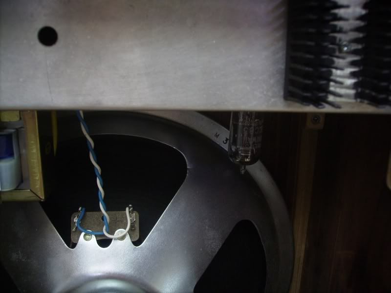
Towrds the centre of the chassis and just above the speaker magnet you can see one of the ground lugs of the aforementioned 50uf + 50uf caps. Just to the left is one of the three bolts that holds it in and around the lug you can just see the cutout in the chassis to make it available to soldering to. I’ll take another photo soon without the circuit board and with all the stuff soldered up in and around that left end of the board… oh, its going to be tight!
Life carries on…
Shit, I am so cash strapped at the moment and when I say that it means I have none and owe heaps… bugger!
Mean
while stuff like this goes on in the world
But life goes on. Had a bit of a chore cutting out the bottom of an old pot to use as a grill for the amp I’ve almsot finished. The blade kept getting aluminium on it so I’d have to stop and take the blade off and cut off the melted on slag with a really sharp knife.

Still needs finesse but I like it and it may be something I could work on and get castings done which could be used for all sorts of things, guitar amps inc.
I’ve built an enclosure for the reverb amp and thats mostly done but I’ve been going hell bent building a tiny tube amp and I don’t just mean tiny in output. The chassis is 40mm x 82mm x 230mm and attached to that or inside are 3 inputs, 4 pots, 4 switches, 2 transformers, 3 tubes and a metre or so of wire plus caps and resistors etc. Its very tightly packed and I’m digging the solutions I have to come up with the get it all together. The output tubes a 6BM8 and the amp’ll be almost the same, in that regard to a 1961 Gibson GA- 5T skylark.
I got the Single ended output transformers from Johnny Pain, bassist of the H Picasso’s, when they were inside an Akai 2 track reel to reel, which decided to blow its power transformer the first time I plugged it in. The PT I’m going to use came from the last gutted chassis I got from Ben at Radio Spares and had a label on the back with the tube compliment and with a little looking up I figured it was good for about 1.5 Amps of filament power so it should cover the tubes I’m using. Just so happens as well that once tested this transformer puts out almost exactly the same B+ voltage as the skylark, within 10V anyways, so I’ll have me an interesting little amp.
The speaker will be mostly for show if it sounds like shit but it’ll have an 8 ohm line out so it’s kinda beside the point and just a bonus if it sounds any good. Okay, I’ll get a photo.

I’ve been back hangin’ at music electronics forums, which is a continuation of the Ampage forums of lore, and a mod came up for how to get more ‘Crunch’ from a 5E3 fender amp and some clever chap came up with a single switch to stack the two channels. I modified it slightly, and got a comp’ from one of the good ol’ boys, so I’ve got one channel with high and low impedance inputs into a 6AU6 pentode, and one other hi channel with a 6AV6, which is basically half a 12AX7, that can switch into the other channels input and make it two stage. Given theres also the third stage, which is the triode of the 6BM8, before the output that should be more than enough to get this thing howlin’.
Doesn’t look like such a tight fit in the photo eh? Well it’s actually inside that aluminium box section chassis where alot is goin’ on and I hope when it comes to the final marrying up of the circuit board to the pots and tubes… I’ll even be able to do it.
I’ve got Reverb… well almost.
I decided to add a tube reverb I made years ago to my arsenal to take to the radio show and trialed it just before I chucked all the stuff into the car for the trip into town. I wanted it just after the first booster and before the phaser and subsequent digital delay so when I was on the backwards delay I could add reverb to it, backwards reverb sounds good!
I hadn’t used the reverb for ages simply because I was never happy with it but on setting it up it gave enough of a result to be worth taking. Trouble was that the power switches were wired in upside down and because of the kinda hurried nature at the radio, the previous guys ran over then one, who plays mean cello, kinda kept me talking when I should have been setting up… so I was late, a little nervous and couldn’t figure why my reverb wouldn’t go, all the while having about 40 seconds left to get sounds so I ditched it, bypassed it, and turned it all on and got some levels. God, what a debacle it was.
I mean I did have fun with it but it was all so hurried and I talked a bit much at the beginning so there wasn’t much time for music at the end and Chris, whos the drummer extraordinaire around town, was kinda waiting to get the jazz show started…
Anyways the long and short of it all is that I took the reverb home and sat in front of it and decided it was worth the effort to either tweak up or rebuild. Conventional spring reverbs are of the fender type where a valve is connected to an output transformer, smaller than a normal one as its only driving the reverb tank, which then transforms the valves high impedance output to a much smaller impedance, 8 ohms, to drive the tanks inductor. But since semiconductors came along the folks at Accutronics in Illinois have been building higher impedance tanks to suit the outputs from opamps. I got one of those because you can actually use valves to drive them but without the weighty and expensive transformer.
But my build suffered from not enough drive to the tank and too much clean signal so it needed lots of boost, with a subsequequent raising of the noise floor, and even then wasn’t the full lush reverb wash I wanted.
With that in mind I decided on a rebuild and after having found a page devoted to using tubes on all the accutronics reverb tanks; low, medium and high impedance inputs, I decided also to change the parallel’d up medium mu (mean basically means voltage amplification factor) valve with a low mu type which, though lower in voltage amplification also means high in current amplification.
Well thats all well and good to decide to use a specific valve but what if you haven’t got one or you have a similar one that runs at another filament voltage? It’s all about choices really, working through them until the compromises suit the outcome you require. At the moment the reverb has two 12SL7 dual triodes so I was going to replace one of the valves with a 12SN7 ( which is similar to the 12AU7) but I haven’t got any 12SN7’s but I do have a couple of 6SN7’s… but the only 6SL7 I have is in an amp…?
I can use 12V valves or 6V valves as the filament supply I have on the reverb is 12V so I can parallel up 12V valves or have two 6V valves in series. I could have used a 12AU7 but those are more modern 9 pin small glass and the ones I’m currently using are octals which sit on bakelite bases and are much bigger and aesthetics are important to me.
So I made my decision to take the 6SL7 out of the moonlight amp and interchange it until another one arrives. So last night I gutted the reverb and rewired the chassis for two 6V valves in series. I’d also drawn up a schematic and etched a board to use pins in a style that predates PCB’s but postdates point to point wiring. This particular style of working allows you to change parts easily as you tweak the design.
This is a major consideration with valves because they often need various parts changed but point to point wiring, which very good for long term use, is very hard to cut into to make changes on the fly.
My next consideration is whether the back to back power transformers I have will supply enough power now that I’ve added a lower voltage amplication/ higher current amplification tube. The 12SL7’s are biased for about 1 – 2 mA whereas the 12SN7’s require at least 5mA and when using back to back transformers that small difference is quite considerable as the change fro 12V up to 240V is x20 so the current needs are also x20.
The back to back thing works where the first 240/12 transformer supplies the filament voltage and current, 6SL7 and 6SN7 require 900mA, and then you go back into the low voltage windings of another transformer and out the other end your back up to high voltage for the valve plates. The transformers I’ve got are 15VA which means Volts Amps, which is basically Watts, so 12.5 Volts, the filament voltage, divided by 15VA = 1.25 A – .9 =.35. That means I have 350mA at 12V to chuck into the next transformer. The voltage goes up and so the current goes down and . I decide to go into the 15V winding which give me a B+ of 190Vrms and a peak voltage of 270VDC. Into the 15 and out the 240 is a change of 16 so my .35A becomes .021 or 21mA… oops I’m going for peak voltage so the 21mA is divided by .7 which leaves me 7/10’s of 21 which is about 15mA which is just about enough to drive two 6SL7 triodes and two current hungry 6SN7 triodes in parallel.
This is the trouble with not having so much money. You have to do all these calculations to see whether what you’ve got will suffice while also, already having just enough, whether you can push what you have to acheive a little bit more. After all the calculations and looking in boxes and scouting about for parts I can basically rebuild the reverb and only spend about 5 bucks for parts I haven’t got in stock and also have something I can go back into easily to tweak it up.
Before photos go in, I’ll keep you waiting, I also dropped into the rockshop after the interview and had a good look at the Orange Tiny Terror and surmised that it’s size and kinda outlook would be good for an amp I’ve been planning for a while now.

It’s a valve amp switchable between 15 and 7 watts output and runs in class A. Upon getting home I found the schematic and it’s basically a Vox AC10 with a few AC15 ideas to modernise it and it’s output in class AB1 style push pull with the tubes biased really hot and into class A territory. Not quite what I wanted, but I could do it as I have a spare push pull output trannie, but I really wanna do the class A thing single ended. Much more second order, octave, distortion with SE than anything else and thats where warm, cuddly and FAT really happens with valves.
The moonlight just ain’t big enough anymore, plus I’m robbing the 6SL7 from it, and the big amp with multi channels still seems rather a task to get going so it’s definitely on the boards to make a tube amp for performing before the end of the month. Plus I’ve still got two twelve inch speakers so maybe my version of a fenderish twin, of sorts, thats actually more champish with Vox AC10 style preamp…
Incidentally I came across a Weber site that explained the difference between the amounts of ribs on these speakers and how they affect breakup. No ribs, early breakup, some ribs, medium breakup and all ribs… late breakup. My quads got all mediums, the amp I just almost finished has all ribs and I’m pretty sure the last two boxes contain no ribs… which be just right for a single ended amp. I actually want that Neil young ultra saggy and comp’d sound where the amp sounds like it’s straining sound through a three hundred year old set of gold threaded turkish courtisans fishnet stockings. Kinda shady relics as it were.
Now photos.
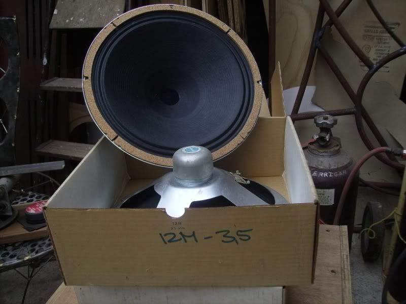
Boringest first. Two old NOS (new old stock) Plessey 3.5 ohm 12″ alnico paper, unribbed, speakers of about 10W.
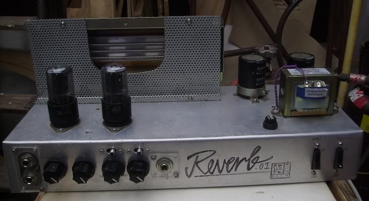
Then we have the old reverb, which I’ll box up in Macrocarpo or Kauri, and you can see in this photo that I modified the reverb tank cage so I can get access to the springs…
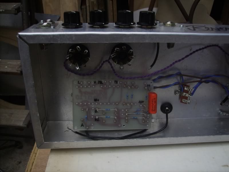
And in this you can see the detail of the new board, which is called turret board, because the little pins that stick up from the board are turrets, and they allow you to wind the ends of the caps and resistors around the pins and solder them on and that process makes removal and changing values quite easy and no dissemble to make tweaks. Wires then run to the pots and power supply, valves etc.
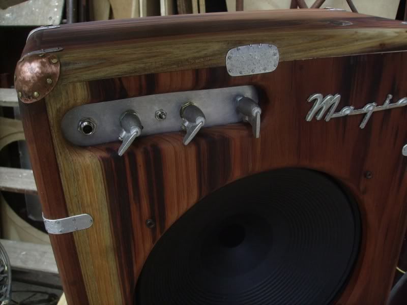
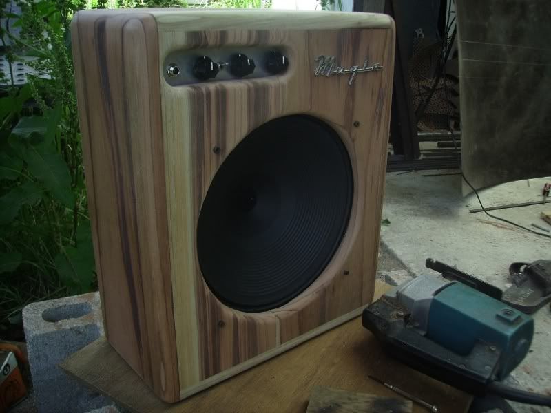
Then we have my new amp, which still needs a grill over the speaker to protect it, a set of feet and a handle for carrying it about but for all intents and purposes it is ready to be plugged in… which I still haven’t done yet so I hope it works!
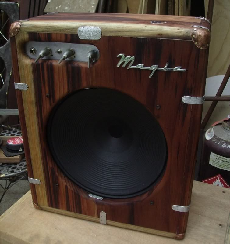
I oiled up the box with some mixture I bought years ago from the Onehunga woodwork tool shop, not quite as good as the oil I got from Patamahoe that’s long gone, but still quite nice, then dirtied it all up again after the process of making the copper corner pieces so I had to resand with wet and dry, using turps, to clean it up of all the smudges, then re-oil it. The knobs are some pewter ones I had cast up a few years ago and the magic badge? Well, like magic itself, I have no idea where I got it from and what it was about but I believe in it so it works!
This is what it looks like from the back, and after reading the Pignose patent notes a few days ago, I’m thinking of covering the rest of the back with a hinged cover, like a window with catches and stuff, so I can set the amount of energy that comes out the back.
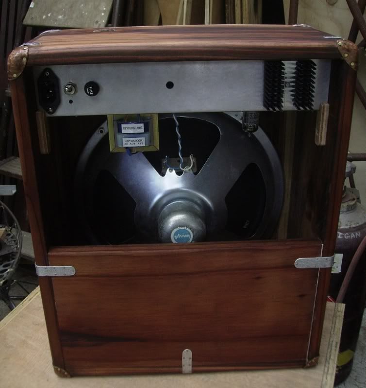
And if you look closely at the above photo you can just see the ECC83 phillips, made in Holland, thermionic valve, but I’ve made it easier (see below). The only thing that concerns me about this build is that B+ and the filament voltage come on at the same time which can mean cathode stripping because the filaments take 11 seconds to warm up and as this happens the plates are at high voltage almost straight away so electrons are immediately ripped from the filament winding and this isn’t a good thing.
Down the bottom of this page , though he doesn’t say it straight out, is a possible way to solve the cathode stripping problem ( thats why valve amps have the extra switch to allow the filaments to warm up before the B+ is turned on; standby). He puts an LED above or below the plate resistor which takes a few seconds to come on and this alleviates the cathode stripping somewhat. Hard to believe you can pass 250V + accross a part that won’t take more than 2V but if he says it’s so then it must be true. It is just a diode though and the fact it not at eart then… I’m just wondering about the current.
So there you go. The valve Wizards pages are very good for understanding how to use valves and how to set them up optimally once you’ve done the background reading ( the .pdf’s by Norman H Crowhurst at Audioexpress.com) and the next one I’ll be into, after the SE amp is the SRPP thing at the bottom of the linked page to fire a bunch of low impedance reverb tanks I have from old amps and organs.
In da Box
I’ve been busy I have. Maybe it’s the Radio thing tomorrow at 11.30… if I keep busy then I’m not answering questions I may not get asked.
the info’s here
So I’ve wired up the little amp and done the box for it and it’s all mocked up ready to be ripped down, the amp tested and tweaked, and the box sanded as smooth as I can be bothered and aluminum and copper added to strengthen and toughen up that which is actually quite soft… then some varnish I suppose…nah, I just oil it up.
And if you look closely below you can jst see the light glinting on the edge of the 12AX7, well it’s actually an ECC83, tube (Valve really, thermionic)
And for anyone interested in building their own here is the schematic.

if you can’t see it properly heres the link to the photobucket page.
Should all work fine, I’m getting pretty good at this stuff, but one always has in the back of ones mind that one day the first plug will come with a bang and some smoke… It’s happened once before… and is actually quite exciting
TDA or not TDA
All amps at the mo’. Read up a little on the TDA2003 and realised the one I’d made was sorted to amplify at 10x but others were using them at 100x so I changed a resistor, divided by ten, and it’s doing everything as it should.
But this small interval between having it not really work to having it work had me designing another one but using a tube… actually I think I wrote about this yesterday… but suffice to say I designed up an amp then went out and found nearly all of the parts I’d need, measured a speaker and found some wood for the box then cut out some aluminium for the electronics to sit in. My plan was to try and make the amp from scratch in one day… but I didn’t make it but I did get this far.
Oops, left the camera plugged into the PC so the batteries have drained again and need charging and it never came with a power supply to run it on 3V. (later on…)

So it’s two stages of tube amplification which is the same as any fender amp from the Golden era then into a j-fet set up as source follower to drive big muff style tone stack, which I suppose I should allow to be bypassed by a switch, then into the TDA2003 at 100x amplification.
I was going to do one of those step by step things, photo essays, pic of the parts, the sheet of aluminium and the plank of wood for the box, the alloy cut and marked, then drilled filed and folded but the camera was on charge… well the batteries (as they are now), so I did it all to the stage of folding up the enclosure and mounting all the hardware.
Today I’m going to make up a small jig of sorts to wire up all the pots to the tag trip and tube base simply because once the chassis is folded it’s really hard to get the stuff soldered up in situ.
The plank is a bit of something or other, an exotic softwood grown here that I picked up in Patamahoe years and years ago and still have enough to make a box and sides. Almost blood red is the wood, so yummy, The speaker is a 12″ alnico magneted Plessey NOS with paper cone and ribs which I also got years ago from a guy in Christchurch. I bought a whole bunch of them for about 10 bucks each and put four in a quad box. Those four sound the best and feature the ribs only around the middle circumference of the speaker cone. The ones I have left, theres three, are either completely without ribs or have ribs all across the cone face. I’ll dig out the other two and use which ever I only have one of for this amp and save the other two for a duo tub at some stage.
I think also that I’ll do a line out on this amp and have a 9V out for fx. The line out will come in handy if I want to do a psuedo stereo thing and maybe send mono signal to this amp then maybe a tremolo into another one.
Always more ideas! Even this morning I thought about doing something with speakers along the lines of the last one in the barbecue tub, the 15″, simply because when I picked it up to move out of the way to photograph the amp chassis, I placed the big speaker tub on top of a frying pan lid and immediately thought that I could suspend a smaller speaker in that… my brain then goes off into the ramifications of crossovers, active or passive?, and how neat it would be to have a whole bunch of different sized speakers suspended in various containers and the whole bunch sitting in a sprung frame so the speakers could flop and jiggle with the sound it emits.
Some chap asked a question about multiple speakers a month or two ago on DIYstompboxes and the consensus was that many the same in series parallel combinations, so it stayed at 8 ohms or whatever, was entirely feasible as long as the wires to the speakers weren’t too long and inductive capacitance became an issue… or was it reactive capacitance. Something beyond my ability anyways that simply means long cables need more power to drive and suffer treble loss which is why systems in buildings, intercoms etc, sound tinny and obscure beyond the cheapness of the speakers… even though they ride the signal on a 50VDC carrier.
I’ve already got unfinished stuff in the pipeline that I’m losing interest in as well as a few projects almost completed that I have almost completely lost interest in and I’m now I’m thinking of a radio tower of speakers in sprung shells. Ideas are always fun to play with and often bringing them to reality and the trouble is often brings can be even more fun!
It would be far sounder physically (sounder as in mechanically sound and physically in regard to physics) to suspend the speakers as I have with wire in the openish enclosures but to then add springs, one or two from above and one behind, from the enclosure to the frame.
It’s kinda is making more sense to me because I’ve got absolutely loads of interesting speakers and an active crossover I made a few years ago that was going to be part of a monitoring system for some PC recording.
One more big bit of furniture to store somewhere though but I do have to work up some significantly aesthetically pleasing pieces that bridge the gaps between furniture making, sound sculpture and plain old art to get photos to send to the Pollock Krasner Trust over in NY next year so maybe this is the thing to do?
Then on the back of it I could suspend a reverb plate, ala Felix the incomparable, so the reverse thrust of the speakers, through the ports on the rear, is picked up and fed back into the system… Shit Bro, I want One!
Still searchin
Yesterdays little play with the TDA2003 amp had me trying different speakers on the end of it simply because at such low wattage output the sensitivity of the speaker is all important. Being the enclosure was quite limiting I couldn’t use the 12″ which actually sounded the best and had to make do with a 5″ vifa I had set aside for an eventual set of monitors.
But I’m now warmed up and upon visiting DIYstompboxes I came accross a thread on sticking a 12AX7 tube before the amp and this isn’t a bad idea as theres an old trick where you can use two power transformers back to back to get the power requirements you need to power a tube with both 12V for the filaments and anywhere over 250VDC for the plates.
The first transformer is set up normally. 240 in and 12 out and you run the filaments for the tube on that. Also you’d throw in a diode bridge and get 12-15VDC off that to drive the TDA2003. Then you grab another 240/12 transformer and throw the 12V you already have into the 12V winding of the next transformer and it gets brought back up to the 240VAC on the other end. This is bridge rectified and smoothed with 400V caps because 240VAC rms becomes about 340VDC. This is more than enough to drive the plates on a 12AX7 tube and it may be prudent to knock it down a bit as the max plate voltage for a 12AX7 is something like 300VDC.
Going into 15-18V windings, instead of 12 will cut it down a bit as it’s the ratios that count here and a 240/12 has a ratio of 20/1 whereas a 240/15 has a ratio of 16/1. 12 x 16 = 192, 192 x 1.414 = 270 and thats a bit closer to be suitable for the plates of a 12AX7 tube.
The 1.414 is about changing rms to a peak value as rms means root mean square and is the AC waveform averaged out but because we are charging caps after a set of diodes then those caps will charge to the peak voltage available in the AC waveform.
Incidentally for those of you that might not know. We measure the wall voltage here as 240VAC and what that means is that we have both positive and negative sides to the waveform and the 240 means that we have peaks running from 240 x 1.414 which is 340 to the peaks so when one is zapped the waveform going into your body goes from 340 positive to 340 negative which adds up to 680VAC +/- accross the complete waveform. So the next time someone says that 240V zaps are quite a shock you can say it was actually closer to 700 that nearly found the heart muscle.
Next thing you do is measure your resistance from hand to hand or from hand to foot and you’ll be able to ascertain how much current you’ll actually have passing through your body at the speed of light. My resistance from hand to hand is about 2 megs so 700 / 2,000,000 = .00035 which is just about half one thousandth of an amp. No wonder they just surprise me. The lower your resistance the higher the current will be and this is why some people get terribly deadly shocks while others merely go “f#ck!” ( a few other things count like perspiration etc, and that counts alot as the salty water is quite a good conductor and so much of the current travels through the perspiration of a sweated person, paths of least resistance and all that.)
But back to amps and I’m going outside to build a little amp using a glass bottle (containing thoriated tungsten), some iron and copper and the odd bit of doped silicon. Hopefully it’ll be louder than all my recent attempts… which still aren’t loud enough to cut above the noise floor at Handmade.
End of the year stuff.
I’ve always found that at this time of year I’m affected by the general malaise that seems to be part of the christmas season. I kinda figured it out years ago after wondering why I would suddenly lose interest as the holidays started and by watching for effects I eventually put it down to the nature of the overlying consciousness at work on all of us.
When the society is out working I can work… but when they decide to do nothing and are thinking of rest (which I incidentally think they think harder about than anything) then all the available creative space seems to be gone and so I just veg until they all get back to work.
This was illustrated last night when a TV star was interviewed about what she was doing for her holidays and after saying several times that she was just going to chill completely for the whole two weeks she then proceeded to explain all the trains, planes and automobiles she’d arranged to be using as she shuffled between three chill out zones.
I’m sorry but I just don’t get that at all. Well I do but I think it’s silly to think one is chilling out while travelling back and forth across the country almost without rest with brief intervals between to acclimatise and before one even gets their bearings and a sense of where they are to be zooming off to some other relaxing place. The sum result being I basically do as little as possible and just let the population at large get it out of their systems.
But we are here for music and related and on that front I did the thing at Handmade last week, the 23rd, and it was yet another working it out kinda gig but it did go rather better than the first one and we ended up almost getting chucked out. My friend Doug joined me and I learned yet again, or remembered, that there is a time and a place for letting those unskilled about the nuances of music making… almost free rein on ones setup. Then Tom turned up, sorry I don’t know his last name, and listened for a while then took over when Doug and I went for coffee down the front.
Whatever huh, but on the promotional side (which is a little scary) I’ll be doing a interview and a little instrument tinkering on Bfm this coming sunday morning. I’m unsure of the exact time right now but it’ll be sometime between 9 and midday on the 3rd.
I love the idea of new experiences, my last little radio interview on said station was way back in the middle of the last decade, but I’m somewhat averse to letting the public know they are going on. I prefer the concept that people are in the right place at the right time which is why I often do things unannounced… even visits accross town. That said I’ll be plugging the Handmade thing, Vitamin S and DIYstompboxes and maybe even this blog.
Back to the Handmade and it’s aftermath. Tom, Doug and myself were down at the car loading the stuff in and discussing the relative merits of the place and the what of its when one of Toms friends arrived in the vicinity and Tom said they were going to be jamming at the Wine Cellar. I dropped Doug off at his studio, can’t call it a house as it’s completely filled up with paintings, offered him my place if I go overseas, and then returned to Town to catch some of Tom and said friend. Tom was on electric guitar and friend was on double bass and they then did some blues. Kinda Cajun blues and I was reunited with the concept of playing guitars normally and the major scale of A. It was great! Both Honkin’ and Tonkin’ were in attendance. I went home and picked up the guitar and realised they’d bin playing in one of my favourite scales.. A major!
But I have done a little work. Below is something I threw together and after finishing I realised it wasn’t what I wanted. It does what I want but the aesthetic is not what I realised I wanted. I’m also quite happy to admit I do actually suffer from that which I sometimes accuse others that being I don’t actually know what I want until I see whats made.

This is the moonlight amp with a speaker, the power supply for the fx, and a container for leads and fx… on wheels.
My unresearched idea for a combo amp. Unresearched because I just let it build itself and because of that it’s far more like a furniture piece than a usable, efficient musical instrument… far too carnivally. But I’m not adverse to the concept but I’ll bin this, as an instrument, and start again I think.
This though is far closer to having something that’ll do the job, pack away nicely yet still retains the ideas of art that appeal to me.

And down there at the back, with all the little holes around it, is the actual amplifier.

Bottom right is the power supply which is 18VDC at a little under two amps so it should be enough to give me about 10 watts.

The above is a ten watter using valves so one can see the obvious advantages of using silicon for amplification. The amp chip is a TDA2003, which costs about 5 bucks from RS, and I’m hoping that attaching it directly to the pot will be enough heat sinking for it. The idea being that the holes drilled increase the surface area around the chip, just like a regular heatsink has fins, while also allowing the required scarcity of metal to allow the lowish frequency of molecular vibration that is heat to be able to dissipate. Solid state amps require big power supplies and big heatsinks because to do what you want them to they are actually very wasteful of power. Anywhere from 50 to 75% of the power needed is wasted as heat. So for ten watts of output one needs at least 20 watts of input power and this is why the power supplies, and heatsinks, are so big on SS amps.
So there you go and because of the radio show being moved from Wednesday night to Sunday morning, and lots of peple back at work, I’ve a few ideas up my sleeve about new things I can build that’ll, as usual, go out into the world untested, usually mostly untried, and “try” to make them work!
Tube, or Valve amps, don’t suffer such in adequacies… they suffer other ones. The parts are big and often heavy and use alot of real estate and are expensive, relatively… but they often sound better and tend to last a long time.
Whats free? this is…
Last night we had the end of year bash for vitamin S and it was kinda equal amounts frustration and fun, not at all because I took along an old friends sixteen year old son who aspires to be a drummer, but thats beside the point because at the end Ivan told me there was a monitor in the bin. Well two monitors but only one was working. So this morning I was dropping the young lad at his Dads workplace, but he hadn’t arrived at 6.45 when we got there, so off we went into town to troll through a bin. The bin was full but I’d been told where it was so it was actually really easy to get out. Man it was a really badly packed bin and shame on the people there for such inefficient use of resources… even if they are chucking them out.
Took it home and plugged a mic in and powered it up and it went but not well. Took it apart and popped the hidden switch from line to mic and found a 4 Ohm piezo tweeter on the bench then carved it up to fit. The one in there was an 8 Ohm magnet and winding type and was mounted like the guy was a farmer and using tools from the landrover. Actually it wasn’t too bad but one needs an incredibly long phillips head screwdriver to get the back off and the tweeter replacing had been done without taking the back off and so what could have been quite a nice job wasn’t so good… and the tweeter was the wrong impedance anyways. So I chucked some foam in there, should have found some dacron but was too lazy, and put it together and it was suddenly much, much better. Looked it up on the net and this stuff, active speakers, have all sorts of circuit protection and other stuff but they’re basically just a couple amplifier chips on a heatsink with two speakers…thank God for car stereos and the surfeit of low voltage chips for their use. The most expensive bit on it though would be the power supply and the toroidal transformer… even more expensive than the speaker. I’m tempted to keep it but it’s ugly as sin, like an unfit fat girl in stretchy lycra, so I think I’ll just flick it off to the highest bidder on trade me… though maybe I should take it and see if Ivan the Terrible wants it.
Ivan impressed me the other day by playing a sink… a stainless kitchen one with two springs bolted accross it… beautiful sounds it made too!

To the side of the monster in smooth black injection (ABS) molded plastic is a 15″ jensen picked up years ago at cash coverters and mounted in a barbecue body. I was going to put it on stands but on trying it out as it is, and having some holes in the back, it’s really easy to move it about and get lots of different feedback tones. I’ve gotten four different notes so far and it’s quite easy to play them. I originally planned to use springs but the ones I had weren’t strong enough, as I was going to mount the front face vertically, and it sagged so I replaced them with taunt welding wire but seeing that I’m using it horizontal maybe I’ll go back to the springs as they were fine in that orientation and I’m kinda wondering what it’d sound like with the speaker bouncing up and down.
So I used it last night and my little moonlight just doesn’t cut it and I think it’s time to get the big amp out of hiding. I built a tube amp years ago with lotsa 12AX7’s and 6V6 or 6L6 output valves in push pull but I’ve never fired it up. The case didn’t come out like I wanted and I needed some switches to fire the different channels so into the waiting list option it went. So maybe it’s time to get 15 watts of tube power into my arsenal. What I’m kind of afraid of is that’ll lead into needing to haul around the quad with 4 x 12 but that’d just be silly having to load the car up with that lot every monday just to get the sounds I end up getting used to… what I really need is to build a champ type single ended amp with minimal parts and about 5 watts of power and use my one great 12″ alnico magnet’d ribbed paper cone speaker.
Oh my God, this amp is packed with features and thats gonna be the case at the end of my three year obsession learning how to do it. It’s kind of a super hot rodded fender of the soldano, mesa boogie variety. Black plate unmatched Jan 6V6’s that can be switched btween fixed and cathode bias, switchable Negative feedback or none and then two channels with separate tone and volumes and an effects loop and a balanced/ unbalanced line out off the speaker output. Thats just from memory so I think theres actually more going on but I just can’t remember.

I had it sorted to switch channels using relays so I could footswitch on the fly but my dreams of being a stage centre shreiking solo guitar hero are long gone so I think I’ll change it round to normal everyday switches on the front and rewire the little relay power transformer as a 9V DC out for FX. I look at this and it’s like about 400 -500 bucks worth of parts and maybe 60-100 hours of assembly and design but I suppose a hand wired boutique amp is worth many thousands of dollars, if it does what its supposed to do, and hopefully this will.
So the Vogue badge goes on a aluminium grill and I should get my brother to Tiger skin some bark tan leather and upholster it and then do some beaten copper corner pieces with little bronze or brass screws. Talk about doing Rich on a budget!
Then the reason all of this has even come about is that I had two other people playing my stuff last monday, after I’d had a go, and realised the speaker on the floor wasn’t cutting through so I planned to build a stand for the speaker so it was off the ground at least 600mm and while I was at it I was going to mount the moonlight amp below it because I’ve never gotten around to putting it in a case and I bent one of the valves pins a week or two ago because everythings exposed on the top… so I thought it would be a good idea to bolt it up into a framework of a speaker stand. While I was going over these ideas and how to do it all I got to thinking of, firstly, cutting away most of the body of the amp so the wiring underneath was exposed while also cutting great big holes in what was left to make it even more interesting looking and from there realising the flatness and squareness of it all wasn’t really to my liking so I went to the idea of taking a piece of aluminium sheet and biffing the hell out of it to make a body more in line with the organic forms I use in my welding.
I know it’s bad form, as the aluminium (or steel, copper silver etc) body on all electronics is so for the reason of being a condusive earth plane while also being a cage of sorts to stop the internals acting like antenna to other signals in the ether, but I’d love to do a tube amp almost inside out where the low impedance circuit could be a tracery of jewels strung around the glass bottles and in a hand beaten body that uses a combination of metals, bloody dangerous of course because we’re talking at least 250 Volts DC (hmm, maybe a safety cage around it all) … maybe if I get some money from overseas (Pollock Krasner trust)… or maybe I’ll just fuckin’ do it anyways!
My new saying… If you can’t beat ’em… get weirder!